Understanding the Multimeter's Core Function
A multimeter measures three electrical properties that determine circuit health: voltage (the electrical potential pushing current through a conductor), resistance (how much opposition blocks current flow), and current (the actual amount of electricity flowing). Most DIY applications require only voltage, continuity, and resistance testing, making the device accessible to anyone willing to learn its basic functions.
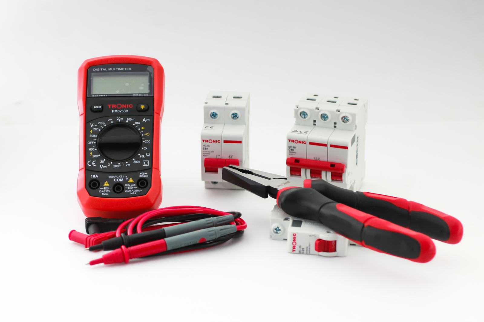
Digital multimeters have become the standard for professionals and homeowners alike because they display measurements as numerals on an LCD screen rather than requiring needle interpretation. The device consists of a display screen, a rotating dial for function selection, colored probe leads (black for common ground, red for positive), and input jacks that accept the probes. Unlike older analog meters, digital multimeters eliminate much of the guesswork from troubleshooting.
A multimeter measures three electrical properties: voltage (the push), resistance (the opposition), and current (the flow). Master these three, and you can diagnose nearly every electrical problem a homeowner encounters.
The Dial: Settings, Symbols, and Function Selection
The rotating dial is where all measurements begin. Understanding dial symbols prevents dangerous mistakes and ensures accurate readings. The dial is divided into sections for voltage, resistance, current, and specialized functions like continuity testing.
Voltage measurements split into two categories: AC voltage (marked with a tilde symbol: ∿V) measures alternating current found in household outlets and mains power, while DC voltage (marked with V⎓ or a straight line over a dashed line) measures direct current from batteries, car electrical systems, and electronic devices. Always select DC voltage when testing batteries and automotive circuits; choose AC voltage only when testing household outlets and appliances.
Resistance is marked with the Greek letter omega (Ω) and typically offers multiple ranges: × 1, × 10, × 100, × 1K, and × 10K. Starting with a higher range (× 10K) prevents damage if the actual resistance is extremely high. Continuity testing, often combined with the resistance function, is denoted by a diode symbol with waves or a sound symbol, and provides an audible beep when current flows freely between two points.
The current measurement sections (marked A or mA) are less common for household troubleshooting but are worth noting. Most multimeters also include a battery indicator, range selector, and specialized modes like MIN MAX (to record high and low values) and REL (to set a reference point).
Measuring Voltage: Battery, Outlet, and Circuit Testing
Voltage testing is the most frequent measurement a DIYer performs. To measure voltage correctly, set the dial to DC voltage (V⎓) for batteries and automotive circuits, or AC voltage (∿V) for household outlets. Insert the black probe into the COM (common) jack and the red probe into the V/Ω jack.
When testing a car battery at rest, a healthy battery should read approximately 12.6 volts. If the multimeter displays 12.2 volts, the battery is only 50% charged; below 12.0 volts indicates a discharged battery requiring recharging. Once the engine runs, the charging system should increase voltage to between 13.7 and 14.7 volts. Readings above 14.7 volts suggest an overcharging alternator that will damage the battery, while readings below 13.0 volts indicate undercharging.
Testing household outlets requires AC voltage selection and careful probe placement. Set the dial to AC voltage with a range of at least 200 volts (standard U.S. outlets deliver 120 volts). Hold both probes in the same hand to prevent current from flowing through your chest if a shock occurs. Insert the black probe into the larger neutral slot (left side of a standard vertical outlet) and the red probe into the smaller hot slot (right side). A reading between 110 and 120 volts indicates a properly functioning outlet; anything significantly higher or lower warrants professional inspection.
When testing individual circuits, probe placement matters enormously. Always connect the red probe to the positive side (higher potential) and black to negative or ground. For DC circuits, reversing probes simply displays a negative value; the reading itself remains accurate. Never allow probe tips to touch one another or bare wires simultaneously when testing live circuits, as this creates a short and may damage the meter or cause injury.
Testing Continuity: The Beep Test for Complete Circuits
Continuity testing detects whether a complete path exists for electricity to flow. This single test answers crucial questions: Is this wire broken? Is the fuse blown? Are the connections solid? The test requires no power—in fact, testing a live circuit with continuity mode can damage the meter or deliver a shock.
Set the dial to continuity (typically a diode symbol with waves or a speaker symbol). Insert the black probe into COM and the red probe into V/Ω. Before testing the actual component, touch the two probe tips together to verify the multimeter is working; a beep confirms readiness. Then place one probe on each end of the component being tested—for example, each end of a fuse or each terminal of a switch.
A beep indicates continuity is present: the circuit is complete and electricity can flow. The absence of a beep or tone means an open circuit exists—a break, corrosion, or failed component blocks current flow. On some multimeters, continuity mode displays numerical resistance; values under 40 ohms typically trigger the audible beep. A reading showing OL (open loop) or 1 on the display confirms no continuity exists.
Always hold both probe handles in the same hand when testing live circuits. This single habit prevents current from flowing hand-to-hand through your chest—the shock path that causes the most severe injury.
Measuring Resistance: Verifying Wires and Component Integrity
Resistance measurement determines how much a material opposes electrical flow, expressed in ohms (Ω). This test identifies broken wires, failed components, and whether connections are degraded by corrosion. Critical safety rule: always disconnect power and ensure the circuit is de-energized before measuring resistance. Testing a powered circuit with the resistance function can damage the multimeter and create a shock hazard.
Select the resistance setting (Ω) on the dial. Start with the highest range (× 10K) and work downward if needed; this approach prevents meter damage if resistance is unexpectedly high. Insert the black probe into COM and the red into V/Ω, then touch each probe to an end of the wire or component.
Interpret the reading: a very low resistance (close to zero ohms) indicates a good, conductive connection or a wire with minimal resistance. Higher readings suggest a corroded or partially broken connection. An OL or 1 display confirms the circuit is open—the wire is broken or the connection is completely failed. When testing wire in an extension cord or electrical cable, move along the entire length while watching the resistance reading; a sudden spike to OL reveals the break location.
Practical Examples: Three Real-World Tests
Testing a car battery provides immediate, actionable data. With the engine off and the battery rested at least one hour, set the multimeter to DC voltage (20V range). Connect the red probe to the positive terminal (usually red, marked with a plus sign) and the black probe to the negative terminal (usually black, marked with a minus sign). Record the resting voltage. Repeat the test with the engine running at idle speed. Compare readings to expected values: 12.6V at rest (fully charged), 13.7–14.7V while running (healthy charging). Below 12.6V at rest or above 14.7V while running indicates a battery or charging system problem requiring further diagnosis or professional service.
Testing a blown fuse is straightforward using continuity. First, remove the fuse from its holder—leaving it installed can create parallel current paths that cause false readings. Set the dial to continuity mode and verify the meter works by touching probes together (listen for a beep). Now position the two probes on the two ends of the fuse, applying firm, steady pressure. A beep means the fuse is intact and conducting current properly. Silence indicates a blown fuse: the internal wire element has melted, breaking the circuit. Visually inspect the fuse element; a blown fuse typically shows a blackened interior or a visible break in the wire.
Testing a household outlet for power involves AC voltage and careful technique. Set the dial to AC voltage at 200V or higher. With dry hands and both probes held in the same hand, insert the black probe into the larger slot (neutral) and the red probe into the smaller slot (hot). The meter should read approximately 120 volts. If the reading is zero, the outlet is dead—either the circuit breaker is tripped or a ground fault has shut off power. If the reading is significantly higher than 120V or lower than 110V, the outlet is faulty and should be inspected by a licensed electrician.
Probe Placement, Safety, and Avoiding Mistakes
Proper probe handling prevents electrical shock, the greatest risk when using a multimeter. Hold both probe handles in the same hand whenever possible; this prevents current from flowing hand-to-hand through the chest, which is the most dangerous shock path. Never touch the metal probe tips while they contact a live circuit—always grip the insulated handles.
Inspect probes before each use. Cracks, splits, or worn insulation expose conductors and create shock hazards. Replace damaged leads immediately; they are inexpensive and easy to swap. When inserting probes into jacks, ensure the connections are firm and fully seated to prevent arcing or intermittent contact.
The critical rule for jack selection: the input jack must match the dial setting. If the dial is set to voltage (V), the red probe must be in the V/Ω jack, not the amp jack. Inserting a probe into the wrong jack can damage the meter's internal fuse and disable the device. Some multimeters feature banana-style connectors that prevent accidental insertion, while others require manual insertion—double-check every time.
Remove all metal jewelry before working with electrical systems. Rings, bracelets, and watches can accidentally contact live circuits and create a dangerous arc. Wear rubber gloves rated for electrical work when handling high-voltage circuits (above 240 volts). Never assume a circuit is de-energized; always test with a multimeter or voltage tester first. Finally, if a multimeter ever feels warm, smells of burning plastic, or sparks, stop using it immediately and have it professionally inspected or replaced.